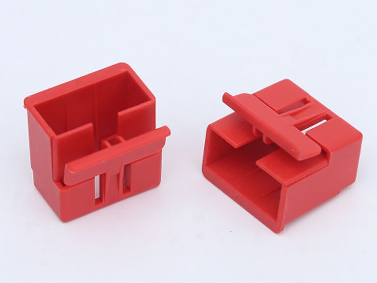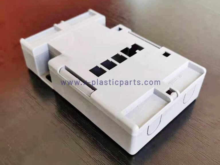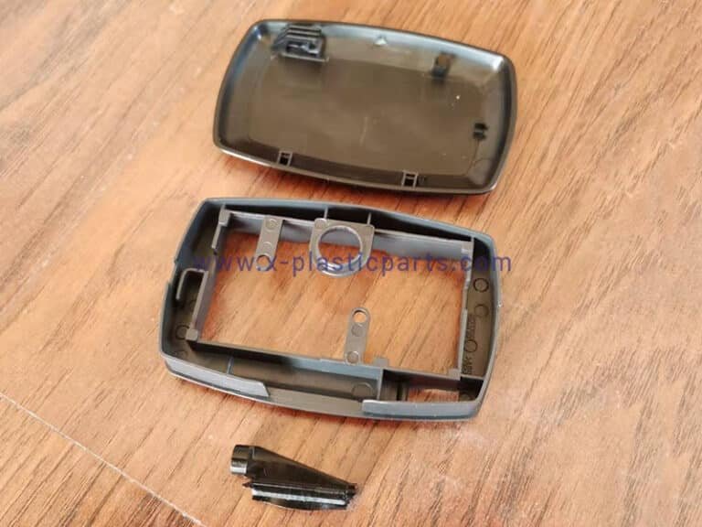
In electronic product structural design, snap fit design is one of the most common methods used for housing assembly. For a broader overview of plastic electronic enclosure design, including wall thickness, ribs, bosses, fastening methods, and other structural considerations, see our guide to electronic enclosure design.
It uses the elastic deformation of plastic materials to create a secure connection without screws or additional fasteners. Proper snap fit design can improve assembly efficiency, reduce component costs, and simplify the overall product structure. This article discusses some design details and characteristics of electronic enclosure snap-fits.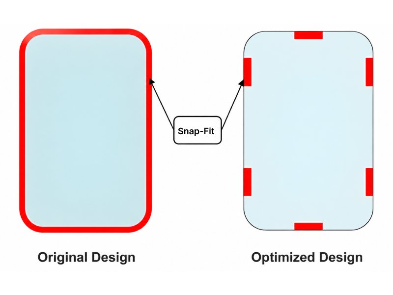
1. Snap Fit Layout and Positioning
Snap fits should be distributed evenly around the part whenever possible to achieve balanced holding force and prevent housing deformation.
For areas that are more likely to deform, such as corners or thin-wall sections, snap fits should be positioned closer to these areas to provide additional support. In most plastic housings, snap fit design works together with locating features, such as mating edges and stepped interfaces, to achieve accurate positioning and reliable assembly.
These features are particularly important in a PCB enclosure box, where the housing must maintain accurate PCB positioning while providing secure assembly and sufficient protection.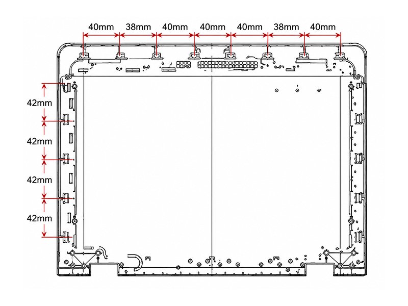
2. Forced-Release Snap-fits
Segmented designs are preferred. These are typically used for parts requiring minimal engagement depth or are designed into flexible plastic sections. The mold utilizes a forced-release ejection method, with an undercut depth generally not exceeding 0.25mm; the harder the material, the shallower the undercut should be. Common examples include bottle caps for personal care products and ballpoint pen caps.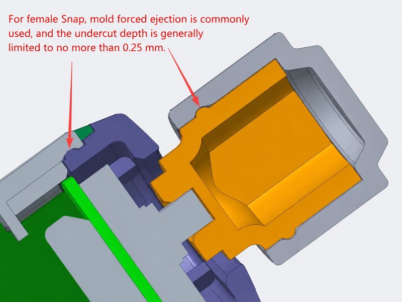
3. Wide Snap-fits
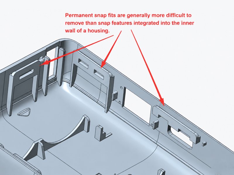
For snap fits with a larger width, the female snap feature may not have enough strength if designed as a single large opening.
A common solution is to divide one large snap feature into two smaller snap structures. Adding reinforcing ribs behind the snap feature is another effective method to increase stiffness and prevent cracking or deformation during repeated assembly.
4. Mold Ejection Considerations
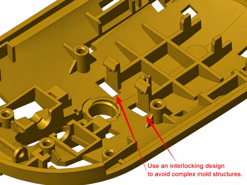
Snap-fit designs must facilitate mold release. Internal structures should avoid interfering with the movement path of lifters or angled ejectors. If a snap feature can be designed using a parting line or shut-off structure for mold release, it is usually preferred over using complex mechanisms such as lifters.
5. Plastic-to-Metal Connections
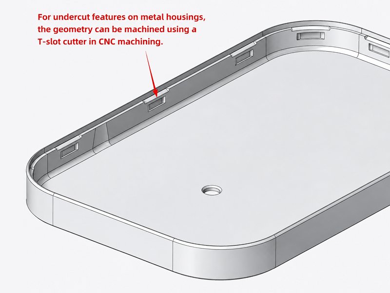
When connecting plastic and metal components via snap-fits, the plastic part usually forms the male tab, while the metal part forms the female receptacle. The metal features are often machined using a T-cutter (T-slot cutter) on a CNC machine.
6. Engagement Depth
The required snap fit engagement depth depends on the application requirements, assembly force, and retention strength. Generally:
- A snap engagement depth below 0.5 mm is considered a flexible or temporary snap fit.
- A snap engagement depth above 0.5 mm is considered a stronger permanent snap fit.
- For applications such as battery covers, the engagement depth can exceed 1 mm to provide stronger retention.
The engagement depth should be balanced with material properties, assembly requirements, and expected service conditions. Excessive engagement may increase assembly force and create higher stress on the snap feature. This is particularly important in small plastic enclosures, where limited internal space requires a careful balance between snap-fit retention, wall thickness, and component clearance.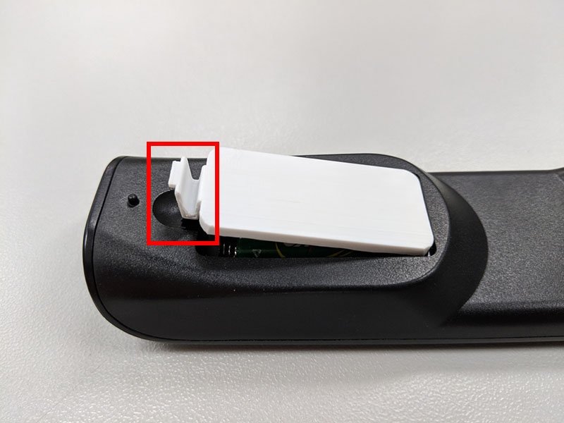
Conclusion
A successful snap fit design requires a balance between holding strength, flexibility, material properties, and mold manufacturability. For a broader overview of snap fits in plastic parts, see our guide to snap-fit design and common applications, material selection, and design considerations.
As an experienced custom plastic injection molding manufacturer, Flexiparts provides professional support in plastic part design optimization, mold design, and injection molding production. Contact us with your product drawings to get suitable snap fit design recommendations for your project.