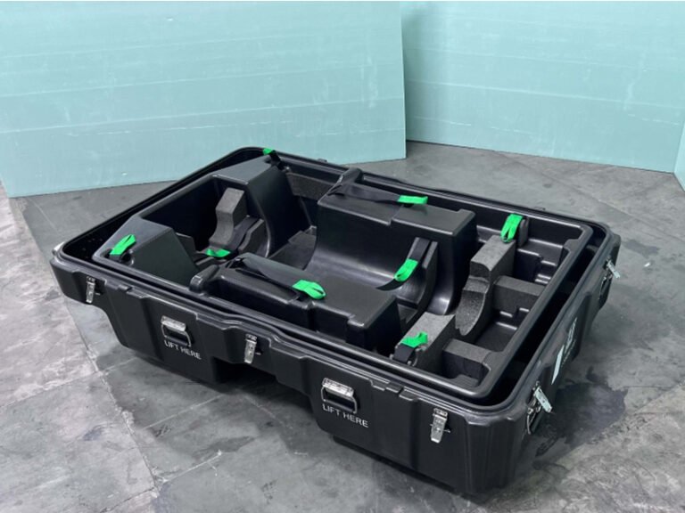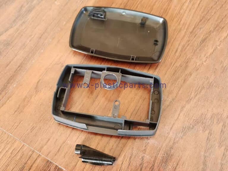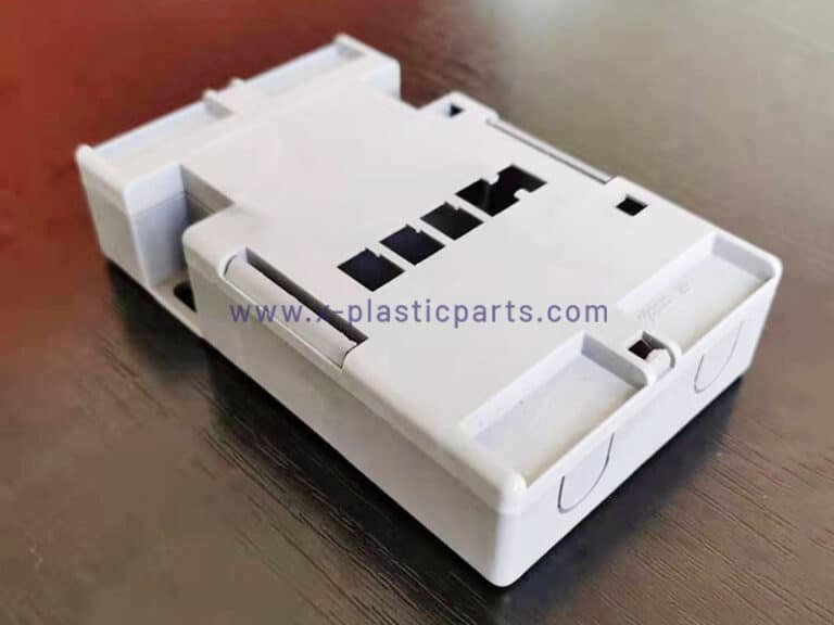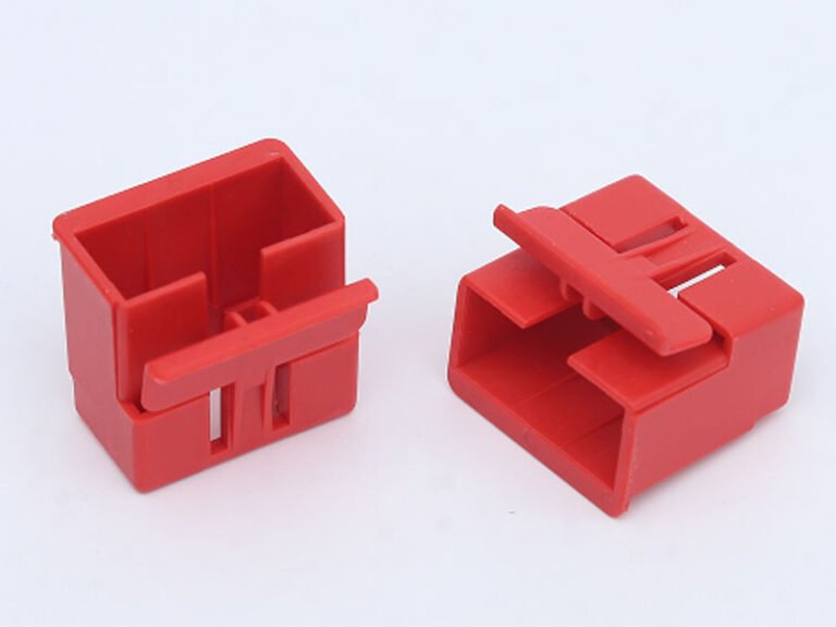
A plastic connector housing forms one essential part of a complete connector assembly. It provides mechanical support, electrical insulation, and protection from the surrounding environment for the metal contact terminals. This article focuses on three practical areas: how to select the right material for a plastic connector housing, how to evaluate design requirements, and how to avoid common manufacturing problems that appear during development.
What Is a Plastic Connector Housing?
A plastic connector housing is the molded polymer body that holds and positions the metal conductive terminals. It does not include the metal contacts themselves. The housing creates the cavities that receive the terminals, maintains the correct pitch between them, and supplies the external features needed for mating, locking, and mounting. In most wire-to-board, wire-to-wire, and board-to-board connectors, the plastic connector housing is the primary structural and insulating element.
Key Performance Requirements for Plastic Connector Housing
The requirements for a plastic connector housing depend on its application. An automotive connector exposed to heat, vibration, oil, and temperature cycling may require a different material and design from a small connector used inside consumer electronics.
Temperature Performance
Temperature performance is often the first filter. Commercial and industrial connectors typically require continuous use temperatures from –40 °C to +105 °C. Automotive under-hood applications frequently demand +120 °C or higher. When the connector undergoes surface-mount reflow soldering, the plastic connector housing must survive peak temperatures of 260 °C without blistering or excessive warpage.
Mechanical Requirements
Mechanical requirements center on strength, toughness, and long-term retention force. Latch and locking features must survive assembly forces and vibration without cracking or permanent deformation. Terminal cavities must hold the contacts securely so that pull-out forces remain within specification after thermal cycling.
Electrical and Flammability
Electrical and flammability properties are equally important. Most applications specify UL 94 V-0 rating. Dielectric strength and comparative tracking index (CTI) must be sufficient for the operating voltage. Moisture absorption, chemical resistance, and dimensional change under humidity also affect long-term reliability, especially in sealed or outdoor connectors.
Common Materials for Plastic Connector Housing
There is no single material suitable for every connector housing. The correct choice depends on which performance requirements have the greatest influence on the application.
PA66 / Nylon
PA66 is frequently chosen for general industrial and consumer connectors. It offers high tensile strength, good impact resistance, and acceptable heat deflection temperature for continuous use up to approximately 105 °C. Its toughness supports robust latch designs. It can be used for various automotive, industrial, and general electrical connectors.
However, nylon absorbs moisture. Moisture absorption can affect dimensions and mechanical properties, so this characteristic needs to be considered when the housing has tight tolerances or operates in humid environments.
PBT
PBT is preferred when dimensional stability and low moisture absorption are critical. Moisture uptake is typically below 0.5 %, so the plastic connector housing maintains tighter tolerances after molding and during service. Continuous use temperatures reach +120 °C in many grades, making PBT suitable for automotive and industrial applications that do not require full reflow compatibility. Chemical resistance to oils, fuels, and cleaning agents is also strong. PBT is therefore a common default for connectors that must hold precise terminal positions over a long service life.
LCP
LCP is often considered for small, precision connectors with thin walls and fine-pitch features. Its flow characteristics make it suitable for filling narrow and complex geometries.
For miniature connector housings, however, the material should be selected together with the mold design and processing conditions. A resin suitable for thin-wall molding still requires appropriate gates, vents, cooling, and injection parameters.
PPA
PPA is suitable for connector applications that require higher heat resistance and dimensional stability than standard engineering plastics can provide. It can be considered for automotive electrical systems and other demanding applications where the housing is exposed to elevated temperatures. Reinforced PPA grades can also provide higher stiffness, although glass fiber reinforcement needs to be considered carefully because fiber orientation can influence shrinkage and warpage.
PPS
PPS is useful when a connector housing must withstand high temperatures and aggressive chemical environments. It offers good dimensional stability and chemical resistance and can be considered for demanding automotive and industrial applications.
The trade-off is that material selection alone does not eliminate molding challenges. Flow behavior, fiber orientation, gate position, and cooling still need to be controlled.
Plastic Connector Housing Design Considerations
The design of a plastic connector housing should focus on the actual features that affect terminal positioning, mating, locking, and injection molding.
Keep Critical Wall Thickness Consistent
Uneven wall thickness can increase shrinkage, sink marks, and warpage. Connector housings often contain thin walls together with thicker bosses, ribs, or mounting areas. The thickness of those areas is typically limited to 50–70 % of the adjacent wall, and they are blended with generous radii to reduce stress concentration.
Design of Latch and Locking Beams
Latch and locking beams require particular attention. Beam length, thickness, and root radius determine both the insertion force and the risk of cracking. A root radius that is too sharp concentrates stress and leads to early failure under vibration or repeated mating. Draft angles on locking surfaces must allow clean ejection without damaging the critical retention geometry.
Plan Gate and Vent Locations
Thin walls and narrow terminal cavities can create difficult filling conditions. Poor gate positioning may result in weld lines, air traps, short shots, or unbalanced filling.
Venting is particularly important around deep cavities and areas where air can become trapped. For complex housings, mold-flow analysis can help evaluate filling behavior before the mold is manufactured.
Tolerance Allocation
Tolerance allocation must account for both the molded plastic connector housing and the subsequent terminal insertion process. Stack-up between cavity position, terminal stamping tolerance, and insertion force can quickly exceed the allowable misalignment for reliable mating.
Consider Draft and Ejection
Connector housings often contain deep cavities, narrow slots, ribs, and small internal structures. These features can make mold release difficult.
Draft angles should be incorporated where the geometry allows. The parting line and ejector locations should also be planned early so that ejector marks or deformation do not affect functional surfaces.
When Insert Molding Is Required for Connector Housings
Insert molding becomes necessary when metal contacts must be permanently embedded in the plastic connector housing with high retention force, precise location, and often environmental sealing. Typical cases include multi-pin headers that experience high vibration, sealed connectors that must maintain IP ratings, and designs where post-mold assembly would introduce unacceptable tolerance stack-up or secondary labor costs.
Insert Molding vs. Post-Assembly
| Aspect | Insert Molding | Post-Assembly (press-fit / snap-in) |
|---|---|---|
| Retention force | High; plastic flows around barbs or undercuts | Lower; relies on interference fit |
| Positional accuracy | High; fixed by mold | Dependent on both housing and terminal tolerances |
| Sealing capability | Excellent; plastic can encapsulate the interface | Limited; potential leak paths around inserted pins |
| Assembly steps | Single molding operation | Separate insertion step after molding |
| Cost profile | Higher tooling and cycle time; lower total at volume | Lower tooling; higher labor and potential rework |
| Best suited for | High-reliability, high-vibration, sealed designs | Lower-cost, moderate-performance applications |
Common Plastic Connector Housing Failures and How to Avoid Them
Several recurring problems appear during development and production of plastic connector housings.
Warpage and Dimensional Variation
Warpage and dimensional drift are among the most frequent. Uneven wall thickness, unbalanced gating, and anisotropic shrinkage in glass-filled grades are the primary causes. Prevention starts with uniform wall design, mold-flow simulation to balance fill and cooling, and selection of a material whose shrinkage characteristics match the required tolerance.
Sink Marks and Voids
Sink marks and voids often form opposite thick sections such as mounting bosses or latch bases. They can distort terminal cavities or create cosmetic defects that are later rejected. Keeping wall transitions gradual and providing adequate packing pressure during molding reduces the risk.
Cracks in Locking Features
Latch or locking feature fracture occurs when the root radius is too small, the beam is oversized for the allowable deflection, or residual stress from molding remains high. Designing the beam for the actual required deflection, adding a generous fillet, and verifying the design with both structural analysis and physical mating tests are effective countermeasures.
Flash and Burrs
Flash can occur along the parting line or around small cavities and functional features. Flash and burrs at the parting line can interfere with mating or sealing. Tight mold maintenance, correct clamping force, and appropriate venting prevent flash from forming in the first place.
Short Shots
Short shots occur when the plastic does not completely fill the mold cavity. Long flow paths, thin walls, insufficient venting, unsuitable material flow characteristics, or inadequate injection conditions can contribute to the problem.
Gate location and wall thickness should be reviewed before production. Adjust melt temperature, injection speed, or gate size.
Conclusion
Although a plastic connector housing is a relatively small structural component, it has a direct effect on the reliability of the entire interconnection system. Correct material selection matched to temperature, precision, and environmental demands, combined with geometry that supports consistent molding and robust locking features, forms the foundation of performance. Appropriate use of insert molding further improves retention and sealing when those characteristics are required.
Flexiparts provides custom plastic connector housing solutions, supporting material selection, DFM analysis, mold design, prototyping, injection molding, and insert molding. Welcome to contact Flexiparts for a custom solution.