
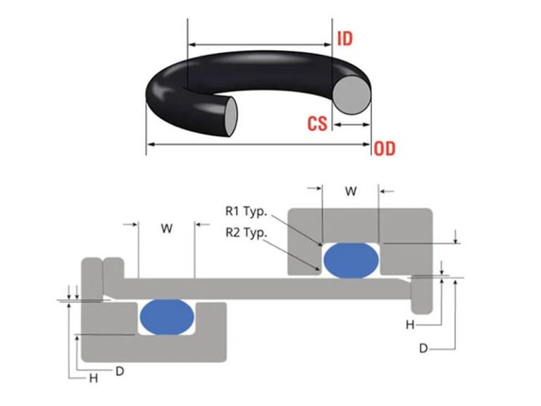
O-ring groove design determines whether a seal actually works, regardless of how good the O-ring material is. The wrong groove dimensions lead to the same handful of failures: leaking, extrusion damage, or premature aging from a squeeze that’s too tight or too loose. This guide explains the main O-ring groove dimensions and design factors, including squeeze, stretch, gland fill, clearance, surface finish, and backup rings.
What Is an O-Ring Groove?
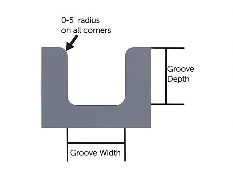
An O-ring groove, or gland, is the machined recess that holds and compresses an O-ring to form a seal. Four dimensions define it: groove depth (how much the O-ring gets squeezed), groove width (how much lateral room it has), corner radii (to avoid damaging the O-ring during installation), and the clearance gap between mating parts.
Select the Seal Type Before Designing the Groove
The first step in O-ring gland design is to determine how the seal will be used.
| Seal Type | Typical Application | Key Requirement |
|---|---|---|
| Face / flange seal | Covers, flanges, end caps | Controlled squeeze and gland fill |
| Dovetail groove | Removable covers and applications where the O-ring must stay in position | Secure O-ring retention |
| Static radial seal | Pistons, rods, housings | Correct radial squeeze and clearance |
| Dynamic reciprocating seal | Hydraulic cylinders, pneumatic systems | Controlled squeeze and low friction |
| Rotary seal | Rotating shafts | Lower squeeze and controlled friction |
Choosing the Right Cross-Section
Larger and smaller O-ring cross-sections trade off in predictable ways, and the right choice depends on which of these factors matters most for a given application.
Small Cross-Section vs. Large Cross-Section
| Factor | Smaller Cross-Section | Larger Cross-Section |
|---|---|---|
| Stability (dynamic reciprocating seals) | Less stable | More stable |
| Friction (dynamic reciprocating seals) | Less friction | More friction |
| Installation space | Requires less space | Requires more space |
| Weight | Lower weight | Higher weight |
| Compression set resistance | Poorer | Better |
| Volume swell in fluid | More swell | Less swell |
| Resistance to explosive decompression | More resistant | Less resistant |
| Gland tolerance requirement | Requires tighter tolerances | Allows looser tolerances |
| Leak risk from dirt, lint, scratches | Higher risk | Lower risk |
| Physical properties (tensile strength, elongation) | Generally better | Generally poorer |
| Cost | Lower | Higher |
| Availability | Generally higher | Generally lower |
AS568 vs. ISO 3601
These are the two dominant sizing standards. AS568 is the inch-based standard commonly used in North America, while ISO 3601 is the metric standard used more broadly internationally, covering both O-ring cross-sections and the corresponding housing (groove) dimensions. The two aren’t directly interchangeable — a groove designed to AS568 tables won’t necessarily match an ISO 3601 O-ring.
When specifying an O-ring, it is good practice to define the standard, size, material, and hardness, rather than specifying only the nominal diameter.
Core Design Parameters
O-Ring Compression and Squeeze
Compression is the percentage reduction in the O-ring’s cross-section once installed. Exact recommended percentages vary somewhat by standard and cross-section series. Still, the pattern holds across all of them: static seals use the highest compression, dynamic reciprocating seals use less to control friction, and rotary seals use the least because continuous motion generates the most heat.
A simple way to calculate radial squeeze is:
Squeeze % = (O-ring cross-section − groove depth) ÷ O-ring cross-section × 100%
O-Ring Stretch and Interference
O-ring stretch occurs when the seal is installed over a larger diameter or into a groove with a different circumference. A small amount of controlled stretch can help keep the O-ring correctly positioned during assembly. Excessive stretch, however, can reduce the effective cross-section and make installation more difficult.
Radial interference is also important because the O-ring needs sufficient contact with the mating surface to seal.
The goal is not maximum stretch or maximum interference. The goal is controlled deformation that keeps the O-ring in position without creating unnecessary stress or friction.
Gland Fill
Gland fill is the percentage of the groove’s volume occupied by the O-ring once compressed. A common target sits around 75%, generally accepted within a 65–85% range. Filling much beyond that risks damage from thermal expansion or fluid-induced swell with nowhere to go; filling too little leaves the seal under-compressed and prone to leaking.
Groove Depth and Width
Groove depth and width are two of the most important O-ring groove dimensions.
For a radial seal, groove depth controls radial squeeze. Groove width provides room for the O-ring to deform under pressure.
For a static face seal, the groove depth controls axial compression, while groove width needs to provide sufficient gland volume.
For dynamic applications, groove geometry must also accommodate movement and control friction.
| O-Ring Cross-Section | Example Groove Depth | Example Groove Width | Typical Application |
|---|---|---|---|
| 1.78 mm | 1.35–1.50 mm | 2.40–2.70 mm | Small static seals |
| 2.62 mm | 1.95–2.20 mm | 3.50–4.00 mm | General static seals |
| 3.53 mm | 2.65–2.95 mm | 4.70–5.30 mm | Medium static seals |
| 5.33 mm | 4.00–4.45 mm | 7.00–8.00 mm | Larger static seals |
| 7.00 mm | 5.25–5.85 mm | 9.00–10.50 mm | Large static applications |
Preventing Failure: Extrusion and Pressure
Clearance Gap and Pressure and O Ring Hardness
Extrusion happens when system pressure forces the O-ring material into the clearance gap between mating parts, where it gets damaged. Three variables control this risk together: Higher pressure + larger clearance + softer O-ring = higher extrusion risk, while a harder O-ring material (higher durometer) resists it better. Reducing the gap, increasing hardness, or adding a backup ring are the three practical levers available when extrusion becomes a concern.
Concentricity and Alignment
Concentricity matters here too. Eccentricity is a static condition — the O-ring isn’t centered in the groove, usually from an installation or manufacturing tolerance issue, leaving one side over-compressed and the other under-compressed. Side loading is a dynamic condition — an operating force pushes the O-ring toward one side of the gland during motion, opening the gap on the opposite side and increasing local extrusion risk. Both produce a similar result but come from different causes, and diagnosing which one is happening points to a different fix.
When to Use Backup Rings?
A backup ring provides additional support for the O-ring and helps reduce extrusion into the clearance gap. For pressure acting primarily in one direction, one backup ring may be used on the low-pressure side. If pressure can act from both directions, two backup rings may be required.
Surface Roughness and Groove Edges
Surface finish on the groove walls affects both sealing and wear.
Surface Roughness
The required surface finish depends on whether the seal is static or dynamic and whether it is sealing a liquid or gas.
| Application | Surface Finish Consideration | Main Reason |
|---|---|---|
| Static liquid seal | Controlled, relatively smooth surface | Reduce leakage paths |
| Static gas seal | Smoother and more closely controlled | Gas can pass through smaller surface irregularities |
| Dynamic reciprocating seal | Smooth and controlled | Reduce friction and wear |
| Rotary seal | Smooth and controlled | Reduce heat generation and seal wear |
Chamfers and Burr Removal
Sharp edges and machining burrs can cut or scrape the O-ring during installation. The groove and the mating component should therefore have suitable entry chamfers, edge breaks, and burr removal.
Special attention is needed around:
- Groove entrances
- Threaded areas
- Ports
- Shaft shoulders
- Assembly transitions
How Material and Working Conditions Affect Groove Design?
Groove design should be considered together with the O-ring material.
Harder durometer materials tolerate larger clearance gaps before extruding but are less forgiving of rough or uneven mating surfaces. Fluid-induced swell changes the O-ring’s effective volume over time, which is part of why gland fill is never designed to 100%. Temperature affects both material stiffness and the amount of thermal expansion the groove needs to accommodate. Since these factors are material-specific, they should be reviewed alongside a proper rubber seal material selection process.
Click here and learn the O-ring material selection guide.
Common O-Ring Groove Design Mistakes
- Selecting the Groove Before the O-Ring: Finalize the O-ring size, material, and hardness before determining the groove dimensions. The groove should be designed around the actual O-ring and application requirements.
- Using the Same Groove Design for Static and Dynamic Seals: Static, reciprocating, and rotary seals have different requirements for squeeze, friction, wear, and surface finish. A groove suitable for a static seal may not work properly in a moving application.
- Ignoring Tolerance Extremes When Setting Squeeze: Do not design around only the nominal compression percentage. Check the minimum and maximum squeeze based on O-ring tolerances and groove manufacturing tolerances to ensure the seal remains within the required range.
- Overfilling the Gland: The groove needs enough free volume for the O-ring to deform and accommodate thermal expansion or fluid-induced swelling. Designing the gland close to full capacity can increase compression and extrusion risk.
- Using Excessive Clearance in High-Pressure Applications: A large clearance gap combined with high pressure can force the O-ring into the gap and cause extrusion. Check pressure, clearance, O-ring hardness, and the need for backup rings together.
- Choosing the Wrong O-Ring Cross-Section: A small cross-section may require tighter tolerances and provide less stability, while a large cross-section requires more installation space and can increase friction. Cross-section should match the available space, sealing motion, pressure, and dimensional requirements.
- Ignoring Surface Finish, Corner Radii, and Burrs: Sealing surfaces need appropriate roughness, while groove edges should have suitable radii or chamfers. Sharp edges and machining burrs can cut or damage the O-ring during installation.
- Relying on a Standard Groove Chart Without Checking the Application: Standard groove dimensions are useful starting points, but they cannot cover every combination of pressure, temperature, fluid, material, hardness, clearance, motion, and manufacturing tolerance. Final groove dimensions should be verified against the actual working conditions.
Custom O Ring Groove Design
Standard AS568 and ISO 3601 sizes cover most applications, but unusual bore diameters, tight installation spaces, or specialized materials sometimes fall outside what a catalog size can support. In these cases, a custom-molded O-ring can be engineered to match a groove that a standard size can’t. If your application needs a custom O-ring or groove dimensions outside standard tables, send us your drawings and operating conditions, and we can help work through the design.