Control arm bushings have a direct effect on suspension movement, wheel alignment, ride comfort, and long-term durability. For buyers sourcing custom or OEM-replacement bushings, however, selecting the right part involves more than matching the outside dimensions of an existing component.
Material hardness, rubber geometry, sleeve dimensions, press-fit interference, bonding method, and void configuration can all change how a control arm bushing performs under load. Manufacturing tolerances also become critical at the sleeve and housing interface, where dimensional variation can affect installation and bushing retention.
This guide focuses on the manufacturing and sourcing considerations behind custom control arm bushings. It covers material options, common dimensions, press-fit tolerances, rubber-to-metal bonding, compliance design, testing, reverse engineering, and production considerations to help engineers and purchasing teams evaluate a custom bushing supplier.
Material Options for Control Arm Bushings
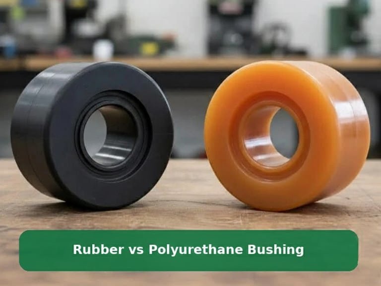
Natural or synthetic rubber remains the most common choice for daily-driver replacement parts, offering good noise isolation and comfort. Rubber compounds can be formulated at different hardness levels to balance ride comfort, radial stiffness, and fatigue resistance. For most automotive suspension applications, the appropriate hardness should be determined by the vehicle’s load, bushing geometry, and required stiffness rather than hardness alone.
Polyurethane (PU) bushings generally provide higher stiffness and better resistance to wear and permanent deformation than conventional rubber. They are often selected for performance-oriented or heavy-load applications where maintaining suspension geometry is a priority. However, higher stiffness can also transmit more vibration and road noise into the vehicle.
Hydraulic, fluid-filled bushings combine an elastomer body with an internal damping chamber. By allowing controlled fluid movement, they can provide additional vibration isolation and damping characteristics. These designs are more complex to manufacture and are typically used where ride refinement and NVH performance are important.
For custom projects, material selection should consider hardness, operating temperature, dynamic loading, chemical exposure, fatigue requirements, and the required stiffness in different directions. A harder material is not automatically a better choice if the bushing must also accommodate significant suspension movement.
Common Control Arm Bushing Dimensions
Control arm bushing dimensions vary significantly by vehicle platform and suspension design. Typical dimensions may include:
| Dimension | Typical Range* | Design Consideration |
|---|---|---|
| Outer sleeve diameter | Approx. 28–55 mm | Determines housing fit and available rubber section |
| Inner bore diameter | Approx. 12–20 mm | Must match the mounting bolt and sleeve design |
| Overall length | Approx. 55–120 mm | Depends on control arm geometry and available installation space |
| Rubber wall thickness | Application-dependent | Influences radial stiffness and compliance |
| Sleeve interference | Drawing-specific | Must be matched to the actual housing and installation method |
Tips: These are general engineering reference ranges, not universal specifications. Actual dimensions depend on the vehicle platform, control arm geometry, mounting structure, and required performance.
For exact matching, the most reliable approach is to provide a 2D drawing, 3D model, OEM reference number, or physical sample. The sleeve dimensions, rubber geometry, hardness, and critical tolerances can then be reviewed together rather than selecting dimensions independently.
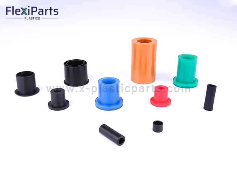
Custom Control Arm Bushing
Manufacturing Considerations for Custom Control Arm Bushings
Sleeve Material and Surface Preparation
Sleeve material affects press-fit retention, corrosion resistance, weight, and bonding performance. Steel sleeves are widely used because of their strength and dimensional stability. Aluminum sleeves can reduce component weight but require careful consideration of surface treatment and long-term interface performance.
For bonded rubber-to-metal bushings, sleeve surface preparation is also critical. Cleaning, blasting, chemical treatment, and bonding-agent application must be controlled before rubber vulcanization. Poor surface preparation can lead to adhesive failure even when the rubber compound itself meets the required specification.
Bonded vs. Non-Bonded Construction
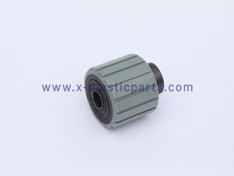
Bonded rubber-to-metal construction vulcanizes the rubber directly to the sleeve, restricting relative movement between the rubber and metal interface. This construction is useful where the bushing must transmit torque and maintain a controlled relationship between the inner and outer components.
Non-bonded designs allow controlled movement between the rubber and sleeve or housing. They can simplify assembly and may be appropriate for applications where rotational compliance is intentionally required.
The choice should be based on the required stiffness, angular movement, installation method, and expected fatigue loading rather than manufacturing cost alone.
Void and Compliance Design
Void geometry is one of the most effective ways to tune the directional behavior of a control arm bushing.
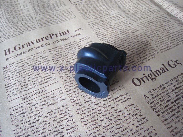
Slotted, offset, or asymmetrical voids can allow greater compliance in the direction where suspension movement is desirable while maintaining higher stiffness in the load-bearing direction. Changing the void size, position, orientation, and rubber wall thickness can therefore alter the bushing’s effective stiffness without simply changing material hardness.
For custom development, the bushing geometry should be evaluated together with the rubber compound because geometry and material hardness work together to determine the final mechanical behavior.
Press-Fit and Dimensional Control
Press-fit performance depends on more than the nominal sleeve diameter. The actual interference is determined by the relationship between the sleeve, bushing outer diameter, and control-arm housing dimensions.
Critical dimensions should therefore be identified on the engineering drawing before tooling begins. Depending on the design, inspection may include sleeve ID/OD, bushing OD, overall length, concentricity, and other application-specific dimensions.
For production parts, dimensional tolerances should be specified according to the actual assembly requirement rather than applying unnecessarily tight tolerances to every feature. This helps balance assembly reliability, tooling cost, and production consistency.
Testing and Quality Inspection
Control arm bushings can be evaluated through a combination of dimensional, material, and performance testing. Depending on the project requirements, testing may include:
- Shore A hardness testing
- Tensile strength and elongation testing of the rubber compound
- Compression set testing
- Rubber-to-metal bonding or adhesion testing
- Dimensional inspection of critical sleeve and bushing features
- Fatigue or durability testing
- Oil and chemical resistance testing
- Heat-aging or thermal exposure testing
- Salt spray testing for metal components or surface treatments, where applicable
Not every project requires every test. The appropriate test program depends on the material specification, vehicle application, customer requirements, and expected operating environment.
Flexiparts Manufacturing Capabilities
Flexiparts supports custom control arm bushing development from drawing review and material selection through tooling, prototyping, inspection, and volume production.
For projects based on an existing OEM component, a physical sample can also be used as a reference for dimensional analysis and reverse engineering. Depending on the part and available information, the development process can include:
- Sample or drawing review — Identify critical dimensions, sleeve configuration, rubber geometry, and application requirements.
- Reverse engineering — Measure the sample and establish the basic 2D/3D geometry.
- Material and hardness selection — Select the rubber or PU formulation based on the required operating conditions and mechanical performance.
- Tooling development — Design the molding tool according to the bushing structure, void geometry, bonding method, and production requirements.
- Prototype production — Produce initial samples for dimensional and functional evaluation.
- Inspection and testing — Check critical dimensions, hardness, bonding, and other agreed test items.
- Production — Manufacture the approved design in production quantities with defined inspection requirements.
Actual dimensional tolerances, MOQ, prototype lead time, and available test reports should be confirmed according to the specific project before quotation. This avoids applying a generic tolerance or lead-time figure to designs with significantly different geometry, materials, or tooling requirements.
Why Control Arm Bushings Wear Out
Control arm bushing failure is usually related to a combination of mechanical fatigue, environmental exposure, material aging, and installation conditions.
Common contributors include:
- Repeated compression and torsional movement
- Excessive suspension loads
- Heat exposure
- Water, salt, oil, and other chemicals
- Incorrect press-fit dimensions
- Excessive installation force
- Misalignment during assembly
- Incorrect tightening position or installation procedure
- Natural aging of the elastomer
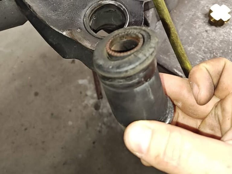
Cracks, permanent deformation, separation between rubber and metal, excessive movement, and changes in bushing stiffness are common signs of deterioration.
For a more detailed explanation of failure mechanisms and prevention, see the guide on why suspension bushings fail.
Work With a Custom Control Arm Bushing Manufacturer
Custom control arm bushing development is not simply a matter of copying the outside dimensions of an OEM part. The rubber compound, hardness, sleeve dimensions, bonding method, void geometry, press-fit relationship, and required compliance all influence the final performance.
Flexiparts supports custom bushing projects based on engineering drawings, 3D models, OEM references, or physical samples. The manufacturing process can be developed around the customer’s required dimensions, material specification, production volume, and inspection requirements.
Send a drawing or sample to discuss the required material, tooling, tolerances, testing, and production requirements for your control arm bushing project.
FAQ
Yes, projects can be developed from an existing physical sample or OEM reference, subject to sample condition and available technical information. The general process is to inspect and measure the sample, establish the required geometry and material specifications, prepare drawings or 3D data for confirmation, and then proceed with prototype tooling and sample production after design approval.
The achievable tolerance depends on the sleeve material, bushing geometry, molding process, and mating housing. Rather than applying one generic tolerance to every control arm bushing, the required interference should be reviewed from the complete assembly dimensions. Flexiparts can evaluate the critical sleeve and housing dimensions from the customer's drawing and confirm the production tolerance during the engineering review.
Testing and inspection reports can be provided according to the agreed project requirements. Typical inspection or test items may include dimensional inspection, Shore A hardness, compression set, rubber-to-metal adhesion, material testing, and application-specific durability or environmental testing. The required test items should be defined before production so that the appropriate test method and acceptance criteria can be established.
Yes. Bushing stiffness can be influenced by material hardness, rubber compound, wall thickness, void geometry, sleeve dimensions, and overall bushing geometry. For this reason, changing the rubber hardness alone is not always the best way to achieve a target stiffness. Custom geometry can be developed when directional compliance or stiffness needs to be controlled.
Yes, custom rubber-to-metal bushing construction can be developed for applications requiring the elastomer to bond directly to metal sleeves. The sleeve surface preparation, bonding system, rubber compound, molding conditions, and post-molding inspection all need to be controlled to achieve consistent bonding performance.