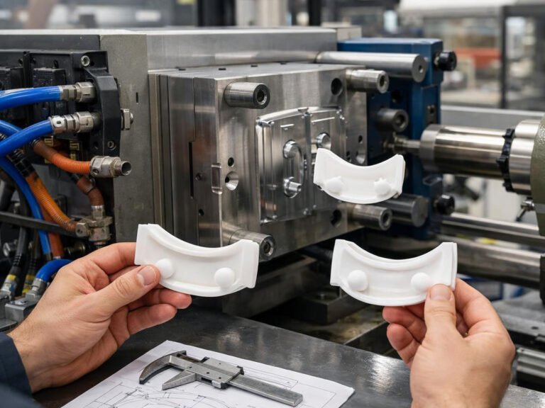
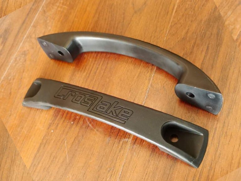
Plastic handle design looks simple from the outside, but its working conditions are not simple. During normal use, a handle may repeatedly experience pulling, lifting, gripping, bending, twisting, and occasional impact. Getting the design right means balancing five things at once: strength, ergonomics, mounting method, moldability, and appearance.
What Makes a Plastic Handle Stronger?
The first step in plastic handle design is understanding how the handle will actually be loaded. A handle may experience several types of force: pulling, lifting, bending, twisting, and impact. The geometry should therefore be designed around the actual load path. Force applied at the grip area has to travel through the handle’s structure to the mounting points, and every transition along that path — where the grip section meets the arm, where the arm meets the mounting boss — is a place where stress can concentrate if the geometry doesn’t support it. Making a handle “stronger” by simply adding thickness everywhere ignores this. A strong plastic handle design is therefore not simply a thick design. It is a design with a controlled load path.
Plastic Handle Wall Thickness
Wall thickness needs to stay reasonably uniform across a handle’s structure. A consistent wall thickness helps the plastic fill and cool more evenly. Large changes in thickness can produce different cooling and shrinkage rates, increasing the risk of sink marks, warpage, voids, and dimensional variation.
A wall that’s too thin lacks the stiffness to resist bending under load and can flex or crack over repeated use. But a wall that’s too thick doesn’t simply add strength — thicker sections cool more slowly than the material around them, and that mismatch shows up as sink marks on the surface, warping as the part cools unevenly, extended cycle time, and less predictable final dimensions. Thickness is a balance, not a safety margin you can just keep increasing.
Use Ribs to Increase Handle Strength
Ribs are one of the most useful structural features in injection-molded plastic parts. They can increase stiffness without requiring a large increase in solid material.
For a plastic handle, ribs are particularly useful around mounting areas, handle roots, bosses, high-stress sections, and long unsupported sections. A rib works by acting like a small beam, resisting deflection along the direction it runs, so orienting ribs to match the actual load direction matters more than simply adding more of them.
However, rib design must also consider molding quality. A rib that is too thick can create a material concentration and lead to sink marks on the opposite surface. A rib that is too thin or too tall may be difficult to fill and eject. As a general starting point, injection molding references often place rib thickness at roughly 40–60% of the adjacent nominal wall, but the appropriate ratio depends on the material, geometry, surface requirements, and molding conditions.
Handle Base Load and Fatigue Design
The handle root is often more critical than the gripping area, because it’s where most real-world handle failures actually happen. The grip area, where a hand wraps around the handle, is rarely the failure point. It’s the base, where the handle transitions into its mounting structure, that concentrates the most stress and sees the most repeated loading cycles. A handle that feels solid in the hand can still fail at the root if that transition isn’t designed for fatigue, not just for a single peak load.
A few design moves address this directly.
- Adding a generous fillet radius at the base softens the transition and spreads stress over a larger area instead of concentrating it at a sharp corner — this is one of the most effective and least expensive changes available.
- Reinforcing the mounting area itself, through a boss, a gusset rib, or local thickening right at the attachment point, gives the highest-stress zone extra material exactly where it’s needed rather than everywhere.
- And sharp internal corners anywhere near the base should be avoided outright — they act as stress risers, and under repeated loading, a sharp internal corner is often where a crack initiates long before the rest of the part shows any sign of wear.
Choose the Right Mounting Method
The mounting method is part of the overall plastic handle design. It determines how the load reaches the housing and how easily the handle can be assembled or replaced.
Screw Mounting
Screw mounting is straightforward to assemble and allows the handle to be replaced later if it’s damaged. The trade-off shows up in boss design: the boss needs enough wall thickness and a properly sized base fillet to resist pull-out force from the screw without becoming so thick that it sinks or cracks.
Snap-Fit Mounting
Snap-fit mounting assembles quickly without separate fasteners and keeps the design lightweight. The features that make this work — the snap arm and its catch — see repeated flexing every time the part is assembled or removed, so material flexibility and fatigue resistance matter as much as the initial assembly force required to snap it into place.
Insert Molding
Insert molding, where a metal threaded insert is molded directly into the plastic, suits high-load applications or handles that will be repeatedly removed and reattached, since a molded-in metal thread holds up to repeated screw engagement far better than plastic threads do on their own.
Integral Molding
An integral handle is molded directly as part of the housing or container. This reduces the number of separate components and can simplify assembly. It can also provide a continuous appearance. The limitation is that the handle and the main housing become one structural system. The connection area must therefore be designed carefully because it cannot simply be replaced as a separate component.
Injection Molding Design Considerations
A good plastic handle design must also work inside the mold.
Draft Angle
Every vertical wall on a handle needs a slight taper so the part releases from the mold without dragging or scraping. Generally, around 1–2 degrees is commonly used for many smooth injection-molded surfaces. Taller features generally need more draft than shorter ones, and ribs need their own draft as well, even though they’re easy to overlook.
Parting Line
The parting line is where the two halves of the mold meet, and it usually leaves a faint line or slight step on the finished part. Placing it away from the grip area, visible cosmetic surfaces, and any functional mating surfaces keeps that line from showing up somewhere it will be seen or felt.
Gate Location
The gate is where molten plastic enters the cavity, and its placement affects how the material fills the part, where weld lines form as separate flow fronts meet, surface appearance near the gate itself, and even structural strength in some geometries. A gate placed without regard to these factors can leave a visible mark or a weak point in a spot that matters more than the designer expected.
Ejection
Where and how a part gets pushed out of the mold affects both appearance and dimensional accuracy. Ejector pin locations can leave small marks on the surface, and if they’re placed on a thin or unsupported section, the ejection force itself can deform the part as it’s pushed free.
Common Injection Molding Defects in Plastic Handles
The defects below are the ones that show up most often in handle production, and each one traces back to a specific design or process cause.
Sink Marks
Sink marks appear as small depressions on a surface, usually opposite a thick section like a rib or boss. They’re caused by that section cooling and shrinking more slowly than the surrounding wall. The design fix is keeping ribs and bosses within a reasonable proportion of the nominal wall thickness rather than letting them balloon at the intersection.
Warping
Warping shows up as a part that doesn’t hold its intended shape after cooling, usually because different sections cooled and shrank at different rates. Uneven wall thickness is the most common design cause, which is why uniform thickness comes up repeatedly throughout handle design rather than being a one-off consideration.
Weld Lines
Weld lines form where two separate flow fronts of molten plastic meet and fuse, typically on the far side of the part from the gate or around an opening the material had to flow around. They can be a cosmetic issue or a genuine weak point, depending on how much the material has cooled by the time the fronts meet — gate location is the main lever for controlling where these lines end up.
Flash
Flash is a thin excess of material that escapes along the parting line or around ejector pins, usually because the mold isn’t clamping tightly enough or the injection pressure is pushing material past a gap it shouldn’t. This is more of a process and tooling issue than a design one, but a design that concentrates pressure unevenly can make it worse.
Short Shots
Short shots happen when the mold doesn’t completely fill before the material cools too much to flow further. Thin sections far from the gate, or geometry that creates a difficult flow path, are common design-side contributors.
Stress Cracking
Stress cracking appears as fine cracks, sometimes not immediately after molding but after the part has been in service for a while. Sharp internal corners, over-tightened screws in a boss, and residual stress from uneven cooling are the usual suspects. Add appropriate radii, reduce stress concentration, review assembly loads, and select a material suitable for the operating environment.
How to Choose the Right Plastic Material?
Material selection should follow the actual requirements of the handle and the plastic material’s properties.
- ABS offers a reasonable balance of impact resistance, rigidity, and cost, which makes it a common default for general-purpose handles.
- PP is more flexible and has better fatigue resistance under repeated flexing, which suits snap-fit designs specifically.
- Nylon holds up well under sustained load and offers better wear resistance than ABS or PP, at the cost of higher moisture sensitivity.
- Polycarbonate provides the highest impact strength and can be specified transparent or in vivid colors, though it costs more than the alternatives.
- Glass-filled nylon adds significant stiffness and dimensional stability for heavy-load or high-temperature applications, at some cost to surface finish and flexibility.
The right choice ultimately comes down to load, operating temperature, impact exposure, environmental conditions, and expected service life considered together, not any single property in isolation.
When to Bring in the Molder for a Design Review?
A design review early in the process, before tooling is cut, is the point where wall thickness, rib placement, draft angle, boss design, parting line location, and ejection strategy can all still be adjusted without cost. Catching a boss that’s too thick, a corner that’s too sharp, or a parting line that lands across a cosmetic surface is far less expensive to fix on a screen than after a mold has already been machined.
For complex or highly loaded handles, mold-flow analysis can also be useful. It can help identify potential filling problems, weld-line locations, pressure requirements, and warpage risks before production tooling is completed.
Conclusion
Effective plastic handle design requires a balance between mechanical performance, usability, assembly, and manufacturability.
If you have a handle design in progress, send us your drawings, and Flexiparts can review wall thickness, rib and boss placement, and moldability before the design gets locked in.