Practical Considerations for Suction Cup Selection
- Suction cup size must generate sufficient holding force. For heavy or asymmetrical parts, multiple suction cups should be used to distribute the load evenly.
- For thin, flexible, or deformable items, increasing the contact area or using several smaller suction cups reduces the risk of deformation and dropping.
- Placement should consider the center of gravity to prevent tilting or unstable movement.
Matching these factors at the start reduces trial-and-error during commissioning.
Step 2: Calculate Required Suction Force
Suction force must exceed the combined weight and dynamic forces of the workpiece, with a clear safety margin. The basic formula is:
F=A×ΔP×η
where
- F is the required suction force in newtons (N),
- A is the effective adsorption area in square meters (m²),
- ΔP is the pressure difference (vacuum level) in pascals (Pa),
- η is the safety factor, typically recommended between 1.5 and 3.0 depending on acceleration, orientation, and safety requirements.
A simplified empirical formula often used in practice is:
F(N)≈0.8×D2×PF (N) \approx 0.8 \times D^2 \times PF(N)≈0.8×D2×P
Where:
- D = Suction cup diameter (cm)
- P = Vacuum level (kPa)
Example
Moving a 2 kg metal part with a safety factor of 1.5 at a vacuum level of –60 kPa. Calculation shows that a cup diameter of approximately 28 mm is the theoretical minimum. In practice, we should select φ30 mm or φ35 mm to provide an extra margin and account for minor surface variations or seal imperfections.
Step 3: Determine Suction Cup Quantity and Layout
- Each suction cup should carry less than 70% of its rated capacity.
- Use at least two cups for rotational stability.
- For elongated or large items, use distributed layouts—three or more suction cups arranged along the centerline improve stability and prevent tilting.
This step ensures reliable gripping even in high-speed or dynamic environments.
Step 4: Select Suction Cup Material and Structure
Material selection affects durability, sealing performance, and environmental compatibility. Structural factors such as cup shape, flexibility, and sealing lip design are also important suction cup design considerations.
Common Suction Cup Materials and Properties

Tips for Material & Structure Selection
Selecting the right material handling suction cup materials based on temperature, chemical exposure, and wear requirements is essential for maximizing suction cup service life.
- Choosing the wrong material or structure can result in poor suction, difficult part release, and reduced productivity.
- For high-temperature or chemically aggressive environments, materials like silicone or FKM are preferred.
- For high-frequency or heavy-duty operations, PU offers longer life and better abrasion resistance.
Step 5: Match the Vacuum System
The suction cup is only the end effector; the vacuum source supplies the power. Two main options exist. Vacuum generators (Venturi type) offer fast response and are ideal for single-machine or independent stations. Vacuum pumps deliver higher flow rates and suit systems with multiple cups sharing a central supply.
Critical checks include target vacuum level (typically –60 to –80 kPa), flow rate in liters per minute, and full airtightness of tubing and fittings. Many instances of dropped parts trace back to an undersized or mismatched vacuum source rather than the suction cup itself. Engineers should calculate total air consumption across all cups and add 20–30 % margin for leaks and response time. Proper system matching ensures consistent performance even under varying production conditions.
Step 6: Optimize Installation Design
Connection specifications usually follow standard threads: M5, M6, or M8. Support methods vary by application.
- Fixed supports provide rigid positioning for repeatable high-speed moves.
- Universal (swivel) supports accommodate angular misalignment.
- Spring-loaded or elastic supports compensate for height variations and reduce impact forces during contact.
Layout principles emphasize symmetry. Suction cup placement must keep the center of gravity centered to avoid eccentric loading. In high-speed cycles, replacing one large cup with several smaller ones can shorten both vacuum and release times, improving overall throughput. Always route tubing to minimize bends and length while protecting lines from abrasion or pinching.
Step 7: Decide Whether Customization Is Needed
Standard vacuum suction cups cover most applications, but certain conditions make customization the more efficient choice.
- Consider a custom design when the workpiece surface is irregular, highly curved, or contains holes that prevent full sealing.
- Thin sheets or membrane materials that deform easily under vacuum also benefit from custom shapes or support features.
- High-speed handling with frequent drop risks often requires specialized lip designs or multi-chamber configurations.
- Environments with heavy oil, dust, or sustained high temperatures may need unique material compounds or protective coatings.
- When installation space is severely restricted and no standard cup fits the available envelope, a custom-molded solution eliminates compromise.
Conclusion
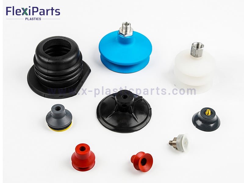
Selecting the right vacuum suction cup is a critical factor in automation success. Systematically evaluate workpiece characteristics, suction force requirements, material and structure selection, vacuum system compatibility, and layout design. When standard products fall short, customized suction cups will improve the effectiveness. Welcome to contact Flexiparts and get a custom solution.