1. Overview of Mechanical Seals
Mechanical seals are commonly used in rotating shaft sealing applications in pumps, reactors, compressors, hydraulic transmission systems, and other similar equipment. They are characterized by good sealing performance, stable operation, low leakage, low friction power consumption, long service life, and minimal wear on shafts or shaft sleeves. In many designs, a rubber bellow is incorporated to accommodate axial and radial movements, absorb vibration, and enhance the overall sealing reliability across a wide range of operating conditions.
According to structural classification, mechanical seals can be divided into spring O-ring type mechanical seals and bellows-type mechanical seals. Bellows mechanical seals have a wide application range, suitable for conditions from low temperature to high temperature, from neutral media to corrosive media, and from low speed to high speed, as well as from normal to severe working conditions. Different bellows materials are selected based on the corrosiveness of the medium inside the equipment.
For Example:
- For neutral media such as water or oil with low pressure and temperature, rubber bellows seals can be used.
- For corrosive media such as acids or alkalis, PTFE bellows seals can be selected.
- For high or low temperature conditions, metal bellows mechanical seals can be used.
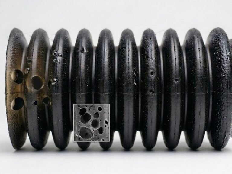
2. Characteristics and Applications of Rubber Bellows
Rubber bellows are used in low-load mechanical seals as auxiliary sealing components, which is why most light-duty mechanical seals adopt rubber bellows structures. Meanwhile, the metal components of rubber bellows mechanical seals are typically stamped parts, enabling efficient mass production through automated assembly lines. This contributes to lower manufacturing cost and good sealing performance, gradually replacing traditional soft packing seals in household centrifugal pumps.
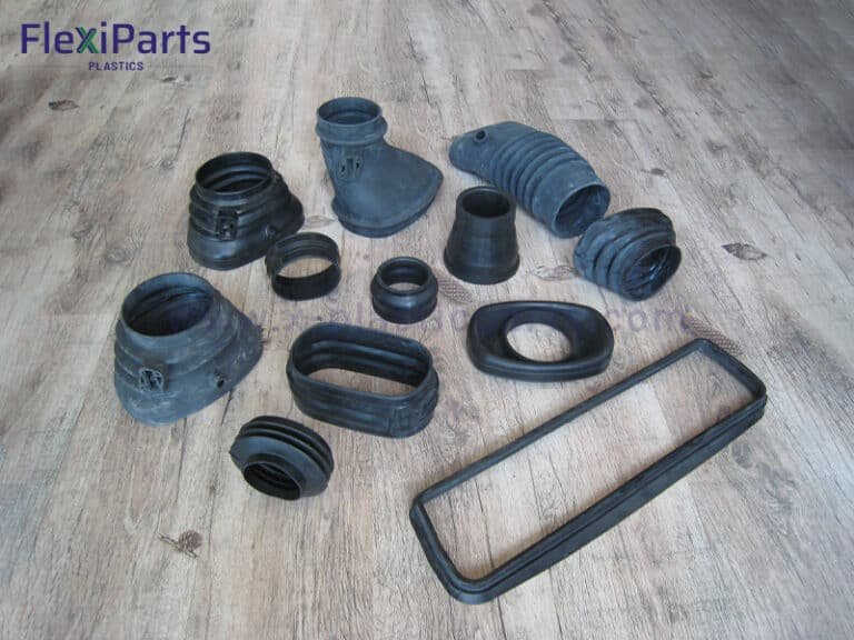
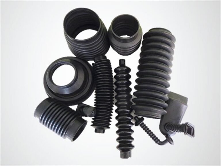
Custom rubber bellows have a wide range of applications. They are mainly used as dust-proof protective sleeves to isolate dust in the air from mechanical components, and can also be used as sealing elements for sealing end faces in mechanical equipment.
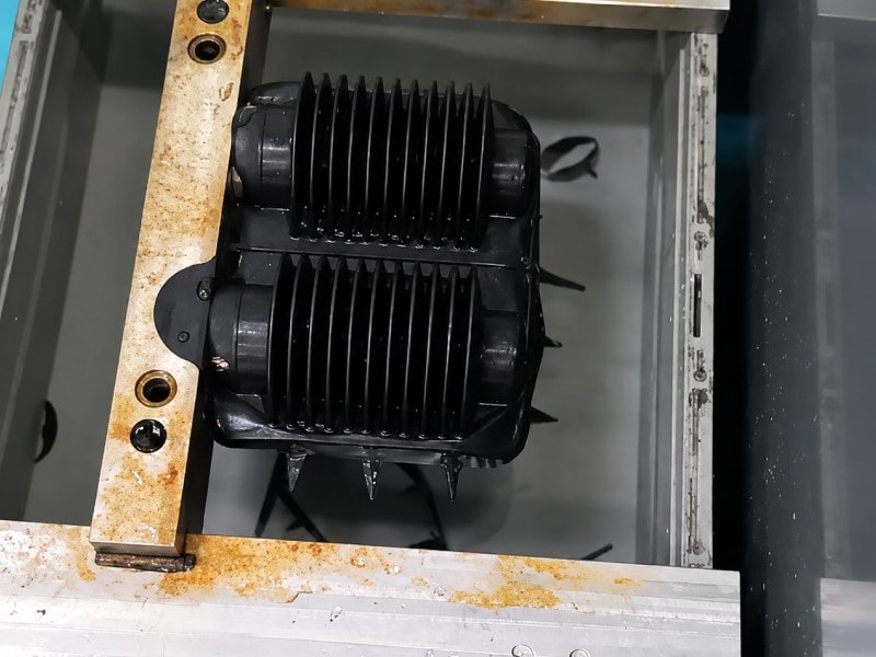
Their forming process generally adopts compression molding. Rubber compression molds refer to the molds used in the compression molding process of rubber parts.
3. Mold Structure Composition and Design Requirements
Molds generally consist of two parts: the cavity (female mold) and the core (male mold). Different products require different mold designs. The compression mold is a critical component, and its structural design directly affects product quality, mold manufacturing cost, production efficiency, and service life.
The main difficulty in mold design lies in the end structure. If the end and bellows section are designed as an integrated mold, machining the boss cavity becomes difficult due to its small size and complex geometry, which cannot be easily achieved with conventional machining methods. Therefore, optimization is required based on structural characteristics.
We adopt a block-injection structure. This structure mainly realizes the complex end cavities and difficult-to-form protruding cavity types by combining the blocks with the mold body. This operation can directly convert the internal shape processing of the protruding cavity types that are not easy to operate into the easier-to-operate external shape processing. At the same time, it also facilitates the processing and measurement of the entire part. It can reduce the processing steps and save costs.
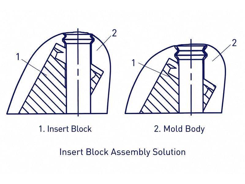
4. Insert Block Structure Design Solution
This design adopts an insert block structure, where the complex end cavity and difficult-to-form boss cavity are realized through a combination of inserts and the mold body.
This approach converts hard-to-machine internal geometries into easier-to-machine external features, while also facilitating overall part machining and measurement, reducing processing steps and lowering cost.
The end cavity consists of two parts, as shown in Figure. Since the end section has a 30° inclined oval-shaped cross-section, the outer contour of the insert must be designed accordingly. This design reduces the number of inserts, simplifies machining, improves assembly accuracy, and ensures cavity dimensional stability.
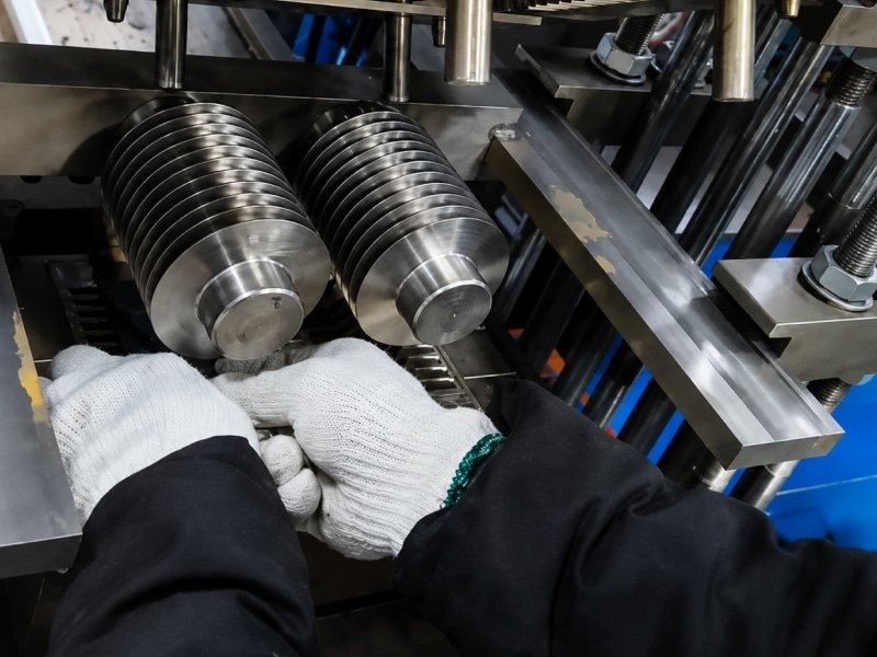
5. Rubber Bellow Mold Processing Technology
Molds generally consist of an inner mold and an outer mold. The outer mold is further divided into upper and lower symmetrical parts. A flash groove is machined on the lower mold to accommodate excess material during processing.
Due to the special shape of the rubber bellows, machining accuracy must be strictly controlled for the inner mold. The inner mold consists of split blocks, stopper blocks, and positioning blocks, as shown in Figure.
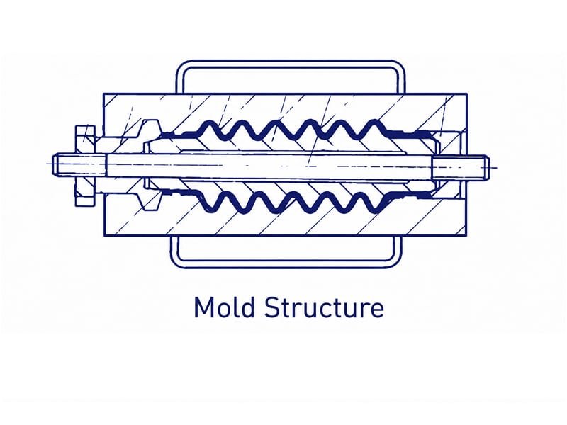
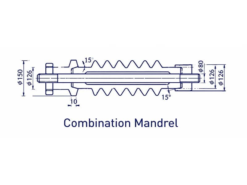
After the inner mold blocks are assembled, they are matched with the outer diameters of both ends of the core rod through internal holes. The two ends of the split blocks are respectively matched with the stopper blocks and positioning blocks at a 15° angle, and then locked onto the core shaft to form the complete structure, as shown in Figure.
After assembly, the clearance between inner mold blocks must be less than 0.01 mm to ensure a smooth inner cavity surface and prevent flash formation.
6. Conclusion
The design and manufacturing process of rubber bellows molds is relatively complex and requires careful attention during production. However, the produced components meet design requirements and achieve a high qualification rate. After process improvements, machining difficulty is significantly reduced, manufacturing cost is saved, and the design demonstrates strong industrial applicability.