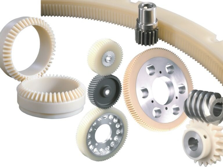
Plastic gears are widely used in various mechanical systems due to their lightweight, corrosion resistance, and noise reduction properties. However, a successful application requires careful consideration of material properties, geometric parameters, and load conditions, etc. Effective plastic gear design ensures reliable performance, long service life, and optimal transmission efficiency. This article provides structured plastic gear design guidelines for engineers, covering key aspects from load analysis to assembly considerations.
Load and Strength Matching
These steps prevent tooth deformation and ensure the gear pair meets operational demands without oversizing the assembly.
- Plastic gears transmit lower torque than metal equivalents, so designers must verify that calculated strength exceeds the applied load. A safety factor of at least 2.0 is standard.
- Tooth width should increase to 1.2–1.5 times the value used for metal gears to distribute bending stress.
- Positive profile shift on the pinion strengthens the root and reduces the risk of fracture under repeated loading.
- Finite element analysis helps simulate stress distribution for steady or shock conditions.
- Service factors range from 1.0 for continuous operation to 2.0 for intermittent high-impact duty.
- Larger modules of 2 mm or more suit heavy loads, while smaller modules fit light-duty instruments.
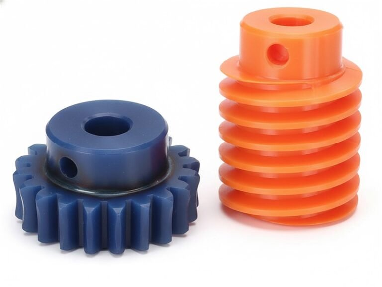
Compatibility and Transmission Efficiency
Material pairing directly affects friction and heat generation in plastic gear design. Self-lubricating resins such as POM reduce the need for external lubricants and maintain efficiency in dry-running conditions. When pairing plastic with metal gears, a 20-degree pressure angle provides standard compatibility. Efficiency improves with a contact ratio above 1.2, smooth tooth surfaces, and controlled backlash. Environmental factors such as humidity increase require clearances by 0.1–0.3 mm to avoid binding. Light lubrication further lowers operating temperatures and extends wear life in higher-load scenarios. The guidelines emphasize that correct compatibility choices minimize energy loss and keep noise levels low throughout the duty cycle.
Gear Parameter Selection
The selection of module, tooth count, and pressure angle forms the core of plastic gear design guidelines. Module starts at 0.5 mm to ensure complete mold filling and reaches 1.5 mm or less for precision instruments. For power transmission, modules of 2 mm or greater provide adequate strength. Pinions require a minimum of 18–20 teeth to avoid undercutting. Standard pressure angle remains 20 degrees; 14.5 degrees reduces noise in low-load applications, while 25 degrees increases root strength. Addendum coefficient of 1.2–1.3 improves meshing overlap for plastics. Backlash allowances exceed metal values to compensate for thermal expansion. Tooth width and fillet radii follow these parameters to maintain uniform load sharing.
Tips: larger modules raise capacity but increase overall size and potential noise.
Tooth Contact and Thermal Analysis
A contact ratio above 1.2 delivers smoother operation and lower vibration in plastic gear assemblies. Fillet radii of 0.2–0.25 times the module reduce stress concentrations at the tooth base. Heat from friction must stay below 60 percent of the material’s melting point. Thermal expansion and moisture absorption require extra clearance in the design stage. Simulation tools predict temperature rise and deformation under sustained load. Materials with lower expansion coefficients help limit dimensional change.
The analysis confirms that creep under continuous torque can alter tooth geometry over time, so operating limits are set conservatively. Regular checks during prototyping validate that contact patterns remain even across the face width.
Shaft Hole Design and Installation
Shaft hole dimensions account for molding shrinkage, which reaches 1.8 percent in POM and 1.2 percent in PA66. Clearances prevent both looseness and excessive binding while transmitting torque reliably. Draft angles of 1–2 degrees ease demolding without distorting the bore. Installation features include generous lead-in chamfers and secure retention methods to stop swinging during rotation. Variable module compensation in the mold maintains roundness after cooling. The guidelines recommend testing assembled units under load to confirm fit stability across temperature and humidity ranges. Proper shaft hole design avoids premature wear at the hub and supports accurate center distance throughout the product’s life.
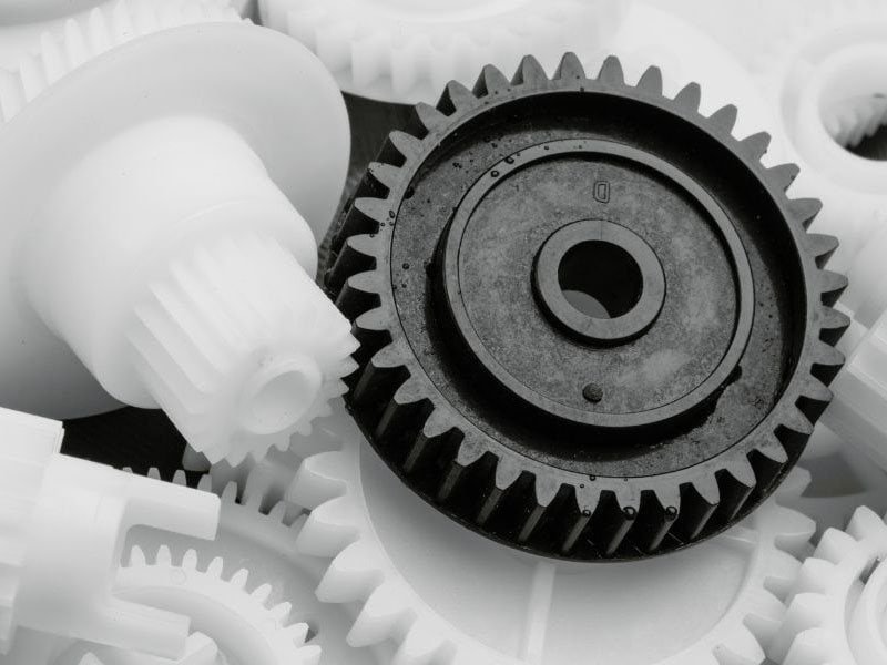
Reinforcement Structures and Material Selection
Wall thickness of approximately 3 mm with variation limited to 15–25 percent promotes uniform cooling and reduces warpage. Ribs add stiffness when their height equals 2.5–3 times the wall thickness, and base thickness equals 0.5–0.75 times the wall thickness. Spacing between ribs exceeds twice the wall thickness to avoid sink marks. For thicker gears above 4.5 mm, a web combined with rim and hub sections distributes load effectively. Material choice depends on environment: POM offers dimensional stability and low friction; PA66 provides wear resistance but requires moisture control; 30 percent glass-fiber reinforcement increases stiffness five- to tenfold. Acetal and PTFE suit specific chemical or temperature needs. These structural and material decisions combat creep and improve fatigue resistance under cyclic loading.
Gear Geometric Parameter Precision Control
Precision in tooth profile, runout, and side clearance keeps transmission error low. Injection molding demands uniform gating and venting to fill teeth. Corner radii and draft angles prevent stress during ejection. Shrinkage compensation through variable module adjustment in the mold maintains target geometry. Tolerances on center distance and backlash remain tighter than metal standards to limit noise and backlash variation. Post-molding measurements verify profile accuracy and lead error. Small deviations in geometry amplify vibration at higher speeds, so quality checks occur at each production stage. Controlled parameters ensure consistent performance across batches.
Conclusion: Plastic Gear Design
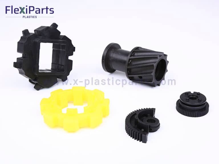
Following the steps produces gears that operate quietly, reliably, and economically in their intended environments. Flexiparts benefit from prototyping and rich experiences to customize each application. Welcome to contact us and get a professional custom plastic gear solution.