Advantages and Disadvantages of Plastic Spiral Gears
Advantages of Plastic Spiral Gears
Lightweight Structure: Plastic material reduces the overall mass and inertia of a mechanical system. This contributes to faster response and higher efficiency.
Quiet Operation: The combination of spiral tooth geometry and the inherent damping properties of engineering plastics results in smoother and quieter motion.
Corrosion resistance: Plastic spiral gears also offer excellent corrosion and chemical resistance, making them suitable for use in humid, wet, or chemically exposed environments where metal gears would corrode over time.
Cost Saving: Plastics are cost-effective and easy to mold, allowing for high-volume manufacturing and complex geometries that would be expensive to machine from metal.
Disadvantages of Plastic Spiral Gears
- Lower Load Bearing: Under high torque or continuous high-speed conditions, plastics can deform or wear faster than metals.
- Thermal Sensitivity: Elevated temperatures can cause expansion, softening, or warping of the material, leading to dimensional instability and changes in backlash.
- Dimensional Instability: Plastic materials also tend to have lower stiffness and strength, which may result in deflection under load. In addition, some polymers are prone to moisture absorption, which can alter mechanical properties over time.
Design Considerations for Plastic Spiral Gears
Material Selection
Select polymers with adequate mechanical properties. Nylon 66 (PA66) provides wear resistance and toughness. Polyoxymethylene (POM) offers low friction and dimensional stability. Add 15-30% glass or carbon fiber to increase modulus by 2-3 times. Avoid unreinforced plastics for loads above 5 Nm.
Helix Angle Optimization
Limit helix angle to 15°-25° in plastic spiral gears. Higher angles increase axial thrust, which plastics handle poorly due to low stiffness. Lower angles simplify mold flow and reduce warpage.
Tooth Geometry Adjustments
Use standard 20° pressure angle. Apply profile modifications:
- Root fillet radius: 0.3-0.5 module to reduce stress concentration.
- Tip relief: 0.01-0.03 mm to accommodate deflection under load.
- Crown thickness is slightly increased to compensate for thermal expansion.
Backlash and Tolerance
Set operating backlash at 0.15-0.30 mm, higher than metal (0.05-0.10 mm). Account for:
- Molding shrinkage: 0.5-2.0% depending on material.
- Thermal expansion: 80-120 × 10⁻⁶/°C.
- Test at maximum service temperature.
Manufacturing Process
Injection molding remains primary for spiral gear manufacturer production. Gate location at gear center minimizes weld lines. Post-mold annealing at 80-100°C for 2 hours reduces residual stress. CNC machining of metal hubs ensures shaft alignment.
Spiral Gear Applications
Automotive Industry: Differential systems, steering mechanisms, power seats, and mirror adjustment systems.
Industrial Machinery: Actuators, gearboxes, conveyors, and automation equipment.
Aerospace and Defense: Control actuators, gear-driven assemblies, and navigation systems.
Robotics and Automation: Robotic arms, grippers, and servo systems.
Consumer Electronics: Printers, cameras, small motors, and smart devices.
Medical Devices: Diagnostic equipment, imaging systems, and precision pumps.
Marine and Energy Equipment: Propulsion systems, pumps, and gear-driven generators.
Conclusion
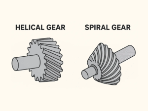
Spiral gears, particularly plastic spiral gears, expand options for efficient transmission. They differ from spiral bevel gears in geometry and use. Common processing methods for plastics include injection molding, with CNC finishing for precision. Spiral gear manufacturers and spiral bevel gear manufacturers continue to refine these components. Contact Flexiparts to explore custom solutions.