How Spur Gears Work?
Spur gears operate through direct tooth meshing. When two spur gears mesh, one acts as the driver and the other as the driven gear. The driver transmits rotary motion through direct tooth contact along the line of action. Force is distributed evenly across the tooth width, producing only radial loads with no axial thrust. This suits parallel shaft setups.
In a spur gear and pinion system, the smaller gear is known as the pinion, while the larger gear is called the wheel. This configuration allows the transmission of torque and speed in opposite directions between two parallel shafts. The speed ratio between them depends on the number of teeth on each gear, which is fundamental to spur gear design calculations.
Materials for Spur Gears
The selection of material directly influences a spur gear’s strength, wear resistance, and cost. The most commonly used materials include:
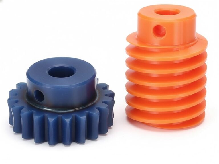
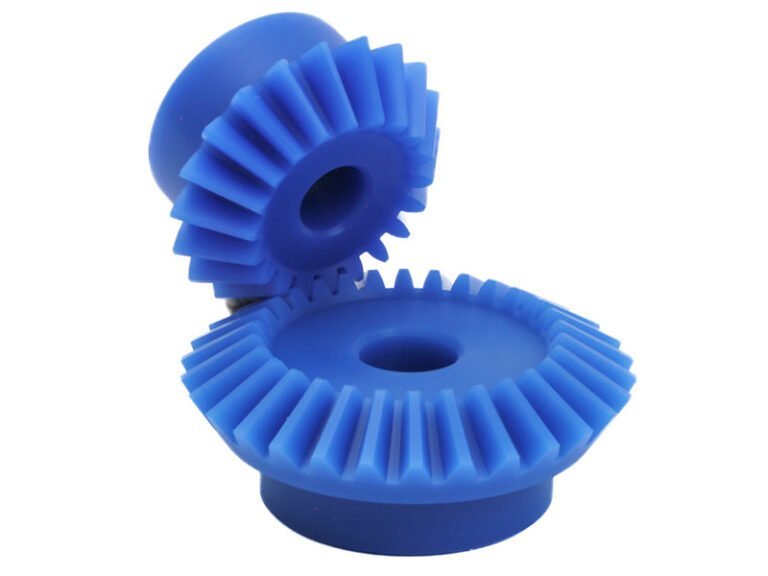
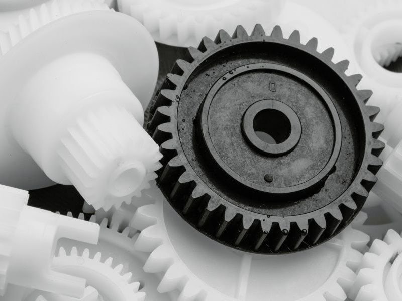
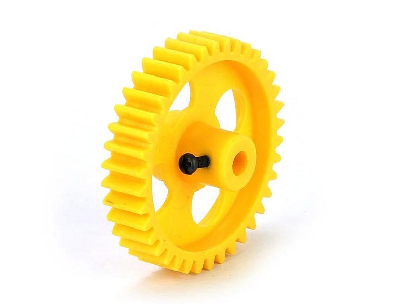
- Engineering plastics: Plastics like nylon or POM are a weight one-seventh of metal and are easy to process.
- Carbon steel and alloy steel: Steel alloys offer high strength and durability. It is suitable for heavy-duty applications.
- Stainless steel: Stainless steel provides corrosion resistance. It is used for food machinery or medical devices.
- Cast iron: Cast iron appears in large gears for vibration damping but adds weight. It is used for low-speed, high-load conditions.
- Brass and bronze: Brass or bronze suits low-noise needs, offering light weight and self-lubrication with corrosion resistance but lower strength. It is suitable for quiet operation and moderate torque systems.
Common Manufacturing Processes for Spur Gears
Spur gear production prioritizes precision and economy.
- Plastic injection molding: This method allows for the mass production of plastic gears with consistent quality. It is suitable for polymer and plastic spur gears in light-duty applications.
- 3D printing: 3D printing is for rapid prototypes and custom designs.
- Hobbing: Hobbing is a standard and efficient method. A hob cutter forms involute profiles continuously along the axis, suitable for volume production with tolerances to DIN 6.
- Gear Shaping: This method handles low volumes, using a forming tool to cut teeth one by one for flexibility. It is used when internal gears or precision requirements exist.
- Powder metallurgy: This is compaction and sintering for low cost and medium strength. It is cost-effective for the mass production of small gears.
Main Types of Spur Gears
Spur gears come in several variations, each serving specific purposes. What are spur gears used for?
External Spur Gears
Teeth located on the outer circumference enable standard external meshing. This type is cost-effective for gearboxes, supports easy shaft alignment, and occupies more space than internal variants.
Internal Spur Gears
Teeth formed on the inner ring create compact assemblies. Common in planetary gear systems, they concentrate torque output and require precise assembly to maintain performance.
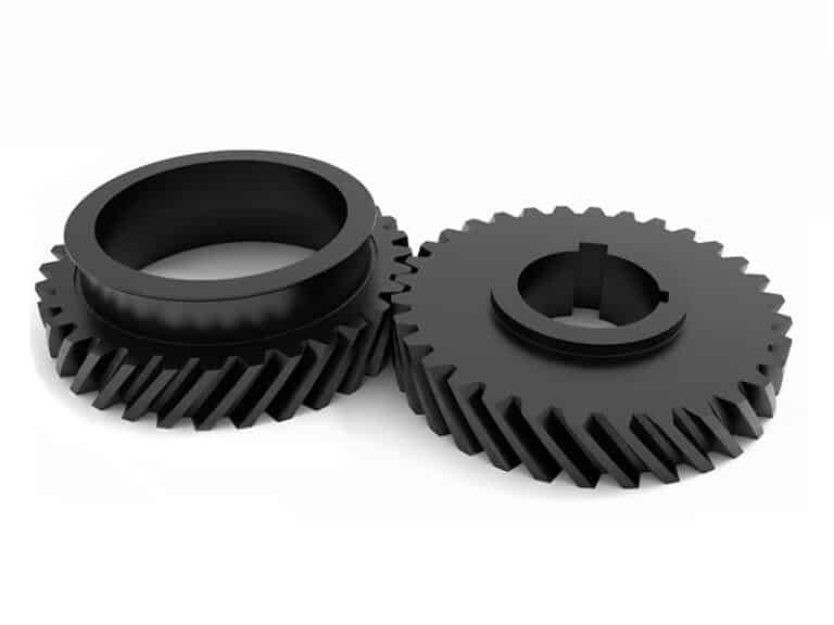
Helical Spur Gears
Teeth angled slightly (8-20°) from the axis combine spur gear simplicity with progressive contact. Noise drops by 20-30 dB compared to straight teeth, enabling smoother operation at higher speeds, though axial forces necessitate thrust bearings.
Double Helical Spur Gears
Two opposing helical tooth sets eliminate net axial loads. This design handles heavy-duty applications like turbines, but manufacturing complexity raises costs.
Rack and Pinion
A straight rack (linear gear) meshes with a circular pinion to convert rotary motion to linear motion or vice versa. Frequently used in steering mechanisms and positioning systems, it provides direct control with a compact layout, though wear rates increase on the rack surface.

Main Advantages of Spur Gears
- Simple and Cost-Effective Design: Spur gears have a straightforward structure that simplifies design, manufacturing, and assembly, making them economical to produce and easy to maintain.
- High Efficiency and Smooth Operation: With minimal sliding friction and a constant velocity ratio, spur gears achieve over 95% efficiency, ensuring stable torque transfer and smooth motion.
- Compact and Flexible: Their design requires minimal axial space, and they can be made from various materials (metals or plastics) to suit different performance needs.
- Durability and Even Load Distribution: Proper alignment ensures uniform load sharing across tooth surfaces, reducing wear and extending gear life.
- Lubrication Compatibility: Spur gears work effectively with various lubrication methods, enhancing operational stability and durability.
- Design Flexibility and Standardization: Engineers can easily adjust gear ratios by modifying the number of teeth, and common profiles ensure easy interchangeability and replacement.
Common Applications of Spur Gears
Spur gears appear across industries for reliable transmission. Key sectors include:
- Automotive: Gearboxes and differentials use spur gears for torque multiplication; electric vehicle motors incorporate them in 40% of designs.
- Industrial Machinery: Pumps and conveyors rely on constant velocity ratios for precise flow control.
- Aerospace: Engines and landing gear employ steel versions to withstand high forces.
- Power Generation: Wind turbines convert energy with high-efficiency spur gears.
- Textile and Printing: Rollers synchronize motion; plastic types ensure lightweight operation.
- Medical and Robotics: Pumps and robotic arms use miniature spur gears for quiet precision.
How to Choose Between Spur Gears and Helical Gears?
The selection between spur gears and helical gears depends on specific conditions. Spur gears excel in simplicity and low cost for parallel shafts, low to medium speeds (under 1000 rpm), and tight budgets, as in basic conveyors. They produce higher noise (over 80 dB) and abrupt engagement. Helical gears offer gradual meshing for noise reduction, higher load capacity (torque up 50%), and suitability for high speeds (over 2000 rpm) or precision in CNC machines, but require thrust bearings for axial forces and double the cost.
Conclusion
When designing or selecting a spur gear, several technical aspects should be considered. Such as gear ratio, torque transmission capacity, alignment accuracy, speed requirements, maintenance convenience, and noise level. For high-load systems, additional design elements such as pressure angle, module or pitch, lubrication method, and surface finish become critical. Flexiparts provides comprehensive solutions for types of gears and custom plastic gears manufacturing. From material selection to prototype manufacturing and mass production. Welcome to contact us for a custom gear solution.